

 0
0
 0
0
By Kelvin Yuk and G. R. Branner
Originally appears: 2011 Midwest Symposium on Circuits and Systems
Microwave frequency multipliers provide a high performance means of generating microwave and millimeter-wave signals in a wide variety of communications and radar systems. The advances in active microwave frequency multipliers due to improvements in technology and design are significant in providing increased conversion gain, efficiency and frequency output. This work overviews the applications, topologies and performance of state-of-the-art active frequency multipliers. Some new circuit techniques are identified.
I. Introduction
Due to the high-cost of developing low phase-noise oscillators, frequency multipliers are often employed with local oscillators (LO) operating at lower frequencies for microwave and millimeter-wave (mm-wave) signal generation [1]. Use of an oscillator-multiplier pair alleviates many design constraints of the oscillator and related circuitry such as in phase locked loops (PLL). Also, although frequency multipliers generate a theoretical 20log(N) phase noise power increase, in practice they still offer better performance than an LO developed at the desired frequency [1].
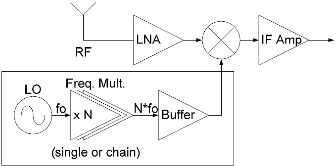
A typical system level implementation of frequency multipliers is shown in Fig. 1a. The LO’s fundamental (fo) output signal is multiplied to the desired harmonic by a single or chained multiplier, amplified by a buffer stage and then delivered to the system. Active multipliers are superior to their passive diode- or varactor-based counterparts in terms of conversion gain (CG) and DC-to-RF conversion efficiency (η). It is frequently necessary to employ buffer amplifier stages to obtain sufficient power, whereas, in the case of many active frequency multipliers, the buffer stage is either unnecessary or its design requirements can be relaxed. Although active multipliers have the potential of achieving gain rather than loss, in most designs, positive CG is sacrificed for increased output frequency operation.
This work provides an overview of the progress in active microwave frequency multiplier development over recent years [2]-[46]. Frequency multiplier development in various existing and emerging technologies is addressed and the current system applications and circuit topologies are summarized. State-of-the-art designs producing high efficiency, CG and power, and mm-wave operation are summarized.

II. System Development
Frequency multipliers are frequently implemented alongside VCOs, PLLs, amplifiers and mixers in a variety of system applications such as transceivers (Fig. 1a), frequency synthesizers (Fig. 1b) [2], downconverters [3], dual-band Wi-Fi transmitters [4] (Fig. 1c) and commercial digital broadcast satellite transceivers (DBS) [5]. Additionally, frequency multipliers are commonly used in mm-wave signal generation for 60GHz future broadband wireless systems [6], automotive radar (Fig. 1d) [7] and phased array applications [8].
In a phase-locked frequency synthesizer (Fig. 1b) the VCO output signal feeds a frequency multiplier which produces the desired output frequency. This reduces the constraints of the PLL and allows its components (frequency divider, phase-frequency detector and low-pass filter) to operate at lower frequencies without sacrificing the output frequency required for the specified application.
A dual-band transmitter scheme for a wireless LAN system is illustrated in Fig. 1c [4]. Both 2.4GHz and 5.8GHz frequencies are necessary under the IEEE 802.11 standard. While two separate modules can be used, it is much more convenient to employ a dual-band transmitter which exploits the fact that 5.8GHz is nearly double that of 2.4GHz. The switchable dual-band scheme uses a bias control to change the output frequency of the LO from 2.4GHz to 2.9GHz and the output mode of the switchable PA/frequency multipler from x1 to x2 operation.
Automotive radar used in adaptive cruise control systems for obstacle detection will improve safety on the road [7]. However, the designated automotive radar frequency, 77GHz, is close to the fT of some technologies, making it difficult to achieve low-phase noise performance on MMICs [3]. Therefore, on-chip frequency doublers, for example, can be used to multiply a 38GHz LO to 77GHz while retaining the receiver operation in 38GHz as shown in Fig. 1d. Frequency multiplication is ideal in automotive radar as well as other types of radar and mm-wave imaging.
In the preceding discussion, we have summarized the use of frequency multipliers in several applications. Many more specific applications of increased complexity exist [8]. Next, the technologies, topologies and state of the art will be summarized.
III. Technologies
Many of the performance improvements and development directions of frequency multipliers are driven by advances in existing and emerging semiconductor technologies. This includes the use of InP [9],[31], GaAs metamorphic HEMT (mHEMT) [32]-[35],[42],[44], SiGe BiCMOS [36]-[38] and AlGaN/GaN (GaN) [25],[29]. Existing technologies like GaAs-based FET devices have also retained a presence as the standard in microwave technology.
Since much of the recent focus of frequency multipliers is in developing MMIC transceivers, advances in micro- and mm-wave generation in CMOS and Si-based technologies are significant in terms of low-cost, high volume commercialization for compact, single-chip transceivers. Hybrids are still prominent for power applications like arrayed systems. So far, the power output of most MMIC technologies cannot match that of PA-oriented technologies like GaN. Several high power GaN-based multipliers have been demonstrated [25],[29].
IV. Topologies
A. Conventional Topologies
A variety of topologies are used for frequency multiplier design. The most conventional ones are single-ended (Fig. 2a), balanced (Fig. 2b) and Gilbert-cell-based (Fig. 2c) [1],[9]. Each has advantages in terms of performance, technology-compatibility and realization. Most single-stage topologies are geared towards either doubler or tripler designs due to practicality. Higher order multipliers are created by using doubler and tripler chains.

Single-ended frequency multipliers employ one active device while balanced frequency multipliers employ two. The devices are biased in a manner which maximizes the production of the desired harmonic that is further embellished by the use of input and output networks which improve CG, output power and the suppression of unwanted harmonics. These networks may contain matching networks, harmonic rejection circuitry and DC biasing feeds. Additionally, balanced frequency multipliers have a signal dividing scheme at the input and combining scheme at the output. For doublers, this input power dividing circuitry is normally a balun which provides two counter-phase signals, one for each transistor. The resulting counter-phase outputs combine, cancelling the output fo while constructively adding the output 2fo. Single-ended topologies consume less power but since their networks rely on tuned elements, it is often difficult to achieve wideband performance. Balanced multipliers provide broadband fo rejection but are more complex and consume more absolute DC power.
Gilbert-cell doublers have both RF and LO inputs connected to the same incoming signal (Fig. 2a). The fo signal subsequently mixes with itself, producing an output rich in 2fo. Gilbert-cells are suitable for CMOS designs and are fully differential, which extends the output swing to twice the supply voltage. This is especially important in CMOS technologies which have a relatively low supply voltage. Gilbert-cells, however, have limited CG and potentially higher DC power dissipation than single-ended or balanced topologies and consume more power since they are biased in Class A, whereas single-ended and balanced doublers can be biased in Class B.
B. New topologies
A variety of frequency multipliers using newer topologies has recently been published including subharmonic mixer (SHM)-based triplers (Fig. 3a) [10], distributed doublers [11] and injection locked frequency multipliers (ILFM) (Fig. 3b) [12]. SHM-based triplers work by mixing the output of a frequency doubler with a fedforward fo signal. The mixer will produce fo and 3fo signals, and the fo can be filtered or eliminated using a subtractor [10]. Distributed doublers improve bandwidth but often have much greater DC power dissipation.


The ILFM uses a relatively new multiplier technique and is well-suited for CMOS (Fig. 3b) [12]. ILFM consists of two cascaded stages: a harmonic pre-generator, which converts the input fo into the desired harmonic, and an injection-locked oscillator, which resonates at the that harmonic [12]. Since the quantification of CG in ILFMs is different from convention (output is bias current dependent, not input power dependent) the comparison tables in Section V do not include CG for ILFMs.
A number of other new techniques have been published. One topology utilizes a common-gate FET, common-source FET configuration whereby the transistor orientation provides the necessary phase shift for balanced operation [13]. The doubler of [14] employs a defected ground structure (DGS) filter which provides a broader bandwidth. Another work uses a left-hand material transmission line (LHM-TL) as a phase shifting element to reduce the size of a balanced doubler [15]. One novel tripler uses a nonlinear combiner which produces “deep cuts” in the fo output waveform to create a strong third harmonic output [16]. Yet another work utitilizes an auxiliary diode tripler which produces supplementary 3fo from the residual fo output of an active tripler [17].
An effort to apply high-efficiency PA techniques to frequency multipliers has arisen due to requirements in low-power systems. This includes the application of class E and class F amplifier techniques to tripler design [18],[19]. The results are frequency triplers which can achieve η of up to 57% [18]. However, like many PAs, many of these techniques result in extremely narrowband performance.
V. State-of-the-Art Frequency Multipliers
This section summarizes many recently published doublers and triplers based on high CG/Pout and output freq performance. These papers consist mainly of work published since 2005.
A. High Conversion Gain / Power
Summaries comparing recently published high CG and output power frequency doublers and triplers are shown in Table I, with the maximum reported CG and Pout (not simultaneous).
B. Millimeter-wave Frequency Multipliers
Most sub-mm-wave frequency multipliers are passive since passive devices have superior bandwidth. However, in the lower and middle mm-wave ranges, active frequency multipliers have better conversion loss and efficiency. Some of these frequency multipliers use newer technologies and push the envelope of solid-state frequency multipliers. Summaries comparing recent mm-wave frequency doublers and triplers are shown in Table II.

VI. Conclusions
Frequency multipliers will continue to play an important part in micro- and mm-wave systems. An overview of recent frequency multiplier developments has been given. New applications, topologies and techniques created in recent years demonstrate the continuing evolution of active microwave frequency multipliers.
References
[1] S.A. Maas, Nonlinear Microwave Circuits, 2nd Ed., Norwood, MA: Artech House, 2003.
[2] T. Baras, A. F. Jacob, “K-Band Frequency Synthesizer with Subharmonic Signal Generation and LTCC Frequency Tripler,” Eur. Microw. Int. Cir. Conf., pp. 466–469, Oct. 2008.
[3] G. Liu, A.C. Ulusoy, A. Trasser, H. Schumacher, “A 60 GHz frequency down-converter with divided LO output in an 80 GHz SiGe HBT technology,” Asia-Pac. Microw. Conf., pp. 936–939, 2010.
[4] J.H. Jeon et al., “A novel dual band transmitter for WLAN 802.11 a/g applications,” MTT-S Int. Microw. Symp., Vol. 2, pp. 1285-1288, 2004.
[5] M. Bhatnagar, H. Morkner, “A low cost SMT integrated frequency doubler and power amplifier for 30 GHz DBS uplink applications,” Eur. GaAs and Other Semic. Appl. Symp., pp. 561-564, 2005.
[6] S.E. Gunnarsson et al., “Highly integrated 60 GHz transmitter and receiver MMICs in a GaAs pHEMT technology,” Jour. of Solid-State Cir., Vol. 40, No. 11, pp. 2174–2186, 2005.
[7] J. Udomoto et al., “A 38/77 GHz MMIC transmitter chip set for automotive applications,” MTT-S Int. Microw. Symp., vol. 3, pp. 2229–2232, 2003.
[8] W.L. Chan, J.R. Long, “A 60-GHz Band 2 x 2 Phased-Array Trasmitter in 65-nm CMOS,” Jour. of Solid-State Cir., vol. 45, No. 12, pp. 2682–2695, 2010.
[9] V. Puyal et al., “A broad-band active frequency doubler operating up to 120 GHz,” Eur. GaAs and Other Semic. Appl. Symp., pp. 557-560, 2005.
[10] B.R. Jackson, F. Mazzilli, C.E. Saavedra, “A Frequency Tripler Using a Subharmonic Mixer and Fundamental Cancellation,” Trans. Microw. Theory & Tech., Vol. 57, No. 5, Part 1, pp. 1083-1090, 2009.
[11] K.-Y. Lin, J.-Y. Huang, S.-C. Shin, “A K -Band CMOS Distributed Doubler With Current-Reuse Technique,” Microw. and Wire. Comp. Letters, Vol. 19, No. 5, pp. 308-310, 2009.
[12] E. Monaco, M. Pozzoni, F. Svelto, A. Mazzanti, “Injection-Locked CMOS Frequency Doublers for u-Wave and mm-Wave Applications,” Jour. of Solid-State Cir., Vol. 45, No. 8, pp. 1565-1574, 2010.
[13] H.-Y. Chang, G.-Y. Chen, Y.-M. Hsin, “A Broadband High Efficiency High Output Power Frequency Doubler,” IEEE Microw. & Wireless Comp. Letters, Vol. 20, No. 4, pp. 226-228, 2010.
[14] S.M. Kang, J.H. Choi, K.H. Koo, S.W. Nam, “A novel 5GHz and 2.4GHz dual band transmitter using microstrip defected ground structure,” MTT-S Int. Microw. Symp., pp. 2259-2262, 2005.
[15] P. Jadpum, J. Tangit, S. Bunnjaweht, “Compact frequency multiplier using an artificial left-handed transmission line,” Elec. Comp., Tele. and Info. Technology Conf., pp. 521-524, 2009.
[16] Y. Zheng, C.E. Saavedra, “A Broadband CMOS Frequency Tripler Using a Third-Harmonic Enhanced Technique,” Jour. of Solid-State Cir., Vol. 42, No. 10, pp. 2197-2203, 2007.
[17] N.-C. Kuo, J.-C. Kao, Z.-M. Tsai, K.-Y. Lin, H. Wang, “A 60-GHz Frequency Tripler With Gain and Dynamic-Range Enhancement,” Trans. Microw. Theory & Tech., Vol. 59, No. 3, pp. 660-671, 2011.
[18] E. Sandhiya, D. Denis, I.C. Hunter, “Novel Design Methodology for High Efficiency Class E Microwave Frequency Triplers,” MTT-S Int. Microw. Symp., pp. 1825-1828, June 2006.
[19] Y. Park, “Class-F Technique as Applied to Active Frequency Multiplier Designs,” Trans. Microw. Theory & Tech., vol. 57, no.12, pp. 2983-2992, Dec. 2009.
[20] S. Mahon, P. Beasty, J. Harvey, A. Bessemoulin, “A broadband millimetre-wave differential pHEMT frequency doubler MMIC,” Comp. Semic. Int. Cir. Symp., pp. 212-215, 2005.
[21] S. Kumar, H. Morkner, “A High Performance 20-42 GHz MMIC Frequency Multiplier with Low Input Drive Power and High Output Power,” Eur. Microw. Conf., pp. 1759-1762, 2006.
[22] W.-R. Lee et al., “A high-efficiency, broadband and high output power PHEMT balanced K-band doubler with integrated balun,” Asia-Pac. Microw. Conf., pp. 763-766, 2006.
[23] B.-J. Haung et al., “A GaAs-based HBT 31-GHz frequency doubler with an on-chip voltage,” Asia-Pac. Microw. Conf., pp. 1-4, 2008.
[24] Y. Wu, X. Chen, H. Wu, B. Liao, “Design of a 4–12GHz frequency doubler MMIC based on InGaP/GaAs HBT process,” Micro. and Milli. Wave Tech., pp. 1045-1048, 2010.
[25] K. Yuk, G.R. Branner, C. Wong, “High power, high conversion gain frequency doublers using SiC MESFETs and AlGaN/GaN HEMTs,” MTT-S Int. Microw. Symp., pp. 1008-1011, 2010.
[26] B. Bunz, G. Kompa, “Broadband HEMT-based Frequency Tripler for Use in Active Multi-Harmonic Load-Pull System,” Eur. Microw. Conf., pp.193-196, 2004.
[27] J.E. Johnson, G.R. Branner, J.P Mima, “Design and Optimization of Large Conversion Gain and Active Microwave Frequency Triplers,” IEEE Microw. & Wireless Comp. Letters, vol. 15, no. 7, pp. 457-459, July 2005.
[28] J.-C. Chiu, C.-P. Chang, M.-P. Houng, Y.-H. Wang, “A 12-36GHz PHEMT MMIC balanced frequency tripler,” IEEE Microw. & Wireless Comp. Letters, Vol. 16, No. 1, pp. 19-21, 2006.
[29] K. Yuk, C. Wong, G.R. Branner, “Design of a high power x-band frequency tripler using a AlGaN/GaN HEMT device,” Eur. Microw. Conf., pp. 612-615, 2010.
[30] S.-W. Lin, H.-C. Chiu, J.S. Fu, “High-efficiency Ka band microwave monolithic integrated circuit frequency tripler using lumped-element balun,” Microw., Ant. & Prop., IET, Vol. 5, No. 1, pp. 30-37, 2011.
[31] V. Radisic et al., “164-GHz MMIC HEMT doubler,” IEEE Microw. & Wireless Comp. Letters, Vol. 11, No. 6, pp. 241–243, Jun. 2001.
[32] Y. Campos-Roca, C. Schworer, A. Leuther, M. Seelmann-Eggebert, H. Massler, “A D-band frequency doubler MMIC based on a 100-nm metamorphic HEMT technology,” IEEE Microw. & Wireless Comp. Letters, Vol. 15, No. 7, pp. 466–468, Jul. 2005.
[33] C. Schworer et al., “A 150 to 220 GHz balanced doubler MMIC using a 50 nm metamorphic HEMT technology,” Eur. Microw. Conf., pp. 565–568, 2005.
[34] Y. Campos-Roca, C. Schworer, A. Leuther, M. Seelmann-Eggebert, “G-band metamorphic HEMT-based frequency multipliers,” Trans. Microw. Theory & Tech., Vol. 54, No. 7, pp. 2983-2992, 2006.
[35] I. Kallfass et al., “A 300 GHz active frequency-doubler and integrated resistive mixer MMIC,” Eur. Microw. Int. Cir. Conf., pp. 200–203, 2009.
[36] G. Liu, A.C. Ulusoy, A. Trasser, H. Schumacher, “64 to 86 GHz VCO utilizing push-push frequency doubling in a 80 GHz fT SiGe HBT technology,” Sil. Monol. Int. Cir. in RF Sys. Meet., pp. 239–242, 2010.
[37] N. Sarmah, K. Schmalz, W. Winkler, C.J. Scheytt, S. Glisic, “122 GHz transmitter using frequency doublers,” Sil. Monol. Int. Cir. in RF Sys. Meet., pp. 157–160, 2011.
[38] L. Wang, Y.-Z. Xiong, B. Zhang, S.-M. Hu, T.-G. Lim, “Millimeter-Wave Frequency Doubler With Transistor Grounded-Shielding Structure in 0.13-um SiGe BiCMOS Technology,” Trans. Microw. Theory & Tech., Vol. PP, No. 99, pp. 1, 2011.
[39] W.L. Chan, J.R. Long, “A 56–65 GHz Injection-Locked Frequency Tripler With Quadrature Outputs in 90-nm CMOS,” Jour. of Solid-State Cir., pp. 2739-2746, 2008.
[40] M.-C. Chen, C.-Y. Wu, “Design and Analysis of CMOS Subharmonic Injection-Locked Frequency Triplers,” Trans. Microw. Theory & Tech., Vol. 56, No. 8, pp. 1869-1878, 2008.
[41] C.S. Yoo, S. Song, K. Seo, “A W-band tripler with a novel band pass filter on thin-film substrate,” Asia-Pac. Microw. Conf., pp. 1-4, 2008.
[42] M. Abbasi, M. Gavell, M. Ferndahl, H. Zirath, “An E-Band(71–76, 81–86 GHz) balanced frequency tripler for high-speed communications,” Asia-Pac. Microw. Conf., pp. 1184-1187, 2009.
[43] F.-H. Huang, C.-C. Chen, H.-Y. Chang, Y.-M. Hsin, “A 20-to-60 GHz CMOS frequency tripler based on a BPSK modulator,” Asia-Pac. Microw. Conf., pp. 2264-2267, 2009.
[44] Y. Kim, Y. Koh, Y. Park, K. Seo, Y. Kwon;, “A CPW-based 77 GHz frequency tripler MMIC using a 130 nm In0.8GaP/In0.4AlAs/In0.35GaAs MHEMTs,” IRMMW-THz Conf., pp. 1-2, 2009.
[45] Z. Chen, P. Heydari, “An 85-95.2 GHz transformer-based injection-locked frequency tripler in 65nm CMOS,” MTT-S Int. Microw. Symp., pp. 776-779, 2010.
[46] S. Ghouchani, J. Paramesh, “A wideband millimeter-wave frequency doubler-tripler in 0.13-µm CMOS,” Rad. Freq. Int. Cir. Symp., pp. 65-68, 2010.