

 0
0
 0
0
By Kelvin Yuk and Sung Park
Written: Dec 4, 2003
Abstract
Investigation of power generation microdevices that utilize micromachining or MEMS for use in portable and self-powered systems. Autonomous and portable devices demand the need for small, lightweight energy supplies that can replace the use of conventional batteries or minimize the replacement or recharging of batteries. The use of MEMS fabrication to create these power generation devices makes them scalable and compatible with continually shrinking distributed and portable electronic systems. Four different power generators using MEMS fabrication or other microfabrication techniques are reviewed. A hybrid thermoelectric generator is then introduced with the potential to extend the power supply lifetime of portable devices. A transmitter application is discussed and from its specifications, a possible design of the hybrid generator is presented.
Introduction
The demand for efficient power schemes extends from the increasing use of portable devices and ad hoc sensor network devices. The power needs of portable devices scale as their complexity and capabilities increase. Battery life is a major design concern in terms of field lifetime of a portable device, especially in environments where recharging is not available. The operation time of a device off of a fully charged power supply can vastly affect the preferences of product consumers and users. The goal of developing new power generation schemes is to design higher density and longer-life power supplies that can offer more lifetime per charge than a traditional battery system.
Likewise, ad hoc sensor networks over a large area are becoming increasingly popular and their devices are becoming more complex, scaling in size and performance. In such networks in which sensor nodes are scattered over a large area, power and lifetime of the devices is a critical concern. The use of batteries in these individual network units is not robust in that batteries are heavy, their lifetime is limited and recharging them is difficult to do over a large, scattered area. The loss of power to just a few nodes in a network may cause the failure of the entire network and so efficient power management is a major concern.
Using disposable devices that are discarded once they have run out of power is not efficient and is costly in terms of time and manufacturing costs. Thus, ideally, a reusable self-powered device that does not need either attention for recharging nor battery replacement is desired. Many new ways of power generation are in development in which resources from the environment harnesses and converted into useable electric power for the sensor or network device. Theoretically, if a device can supply its own power from the environment, its lifetime could be infinite disregarding the aging of the circuitry and sensor components. This would allow networks of a very long operating life, which is advantageous to the user.
Many recent advances in MEMS fabrication and microdevices are allowing many new possibilities in the conversion of external forces and energy into power. The design of precision micro-fabricated devices and mechanics are broadening the techniques for on-chip power generators. Deriving energy from kinetic, solar and chemical processes are being made feasible by precision microstructures. It is the hope that MEMS power generators can provide a high enough output to maximize the operating lifetime of portable electronics and sensors in ad hoc networks.
In this paper, we discuss four MEMS micro power generators, each relying on a different power generation technique. The devices are explained and discussed based on their effective as power capabilities.
We introduce a hybrid device that combines power extraction from both combustion and external radiant heating. Portable devices are the target application for such a generator where recharging of the power supply is possible but cannot be performed often. This dual power extraction provides the advantage of high-density power from chemical combustion as well as extended lifetime and possible self-sufficiency from external radiant heating. A projection of the fabrication stages required to realize the device is presented. Using the formulas and data from [1] and [2], the amount of power than can be harnessed in our hybrid design is estimated and applied to an IR transmitter application.
MEMS Power Generators
Four power generators using MEMS fabrication technologies are selected for discussion. The first two utilize power extraction from kinetic vibrational energy while the second two utilize power extraction from thermal energy.
Kinetic energy as an external energy source for MEMS power generation
Kinetic energy in the form of vibrational motion or rotational motion can be harnessed to produce electrical power. The advantages of using kinetic motion to produce power is that the generator does not need to be supplied with any type of fuel.
Rotational motion has been successfully used in micro electret systems in which a rotor spinning relative to a stator in the presence of an electrically charged dielectric (electret) creates a movement of charges [3, 4]. However an assembly is needed to supply the rotation. On the other hand, vibrational systems are easier to start up. Any vibration is translated in to power while rotation is difficult to generate on a stationary system.
Vibrational motion used to produce power on ICs is made possible by MEMS fabrication, which allow the physical movement of micro assemblies on a single substrate. The generators discussed here utilize vibrational motion, which is often abundantly available especially on the micro scale with which these devices are fabricated. As a result, this type of energy can always be expected from the environment.
While ambient conditions can be used as the energy source, movement or vibration has also shown to be useful in generating power. With the invention of MEMS, micromachined mechanics can be used to convert movement into electrical energy. Some concerns with moving parts of MEMS devices may be the durability of the mechanical device as well as stiction. If force too large is applied to the device, the moveable assembly may be forced into an extreme position, disabling it entirely.
Power Extraction from Ambient Vibration
In [5], the authors develop such a method using the vibration of plates to vary capacitances over a statically charged dielectric (electret).

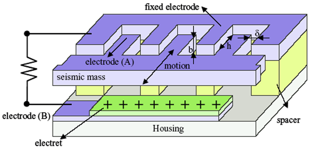
Figure 1. Cross-section of a MEMS based vibration-to-electric generator [5]
A diagram of the MEMS-based vibration-to-electric generator is shown in Figure 1. The generator is composed of a variable capacitor composed of two fixed combed in-plane electrodes and a combed electrode on a moveable seismic mass. The figure shows only one side of the seismic mass and fixed electrode, but the combed electrode A and seismic mass is actually dual sided. The shared variable capacitors here are formed by one side of the combed electrode A and the fixed electrode and the other side of the combed electrode A and another fixed electrode on the other side. As the assembly vibrates, the seismic mass moves on the horizontal plane into and out of the page, changing the capacitance on the two sides of electrode A. The constant charge is provided by the electret that sits atop electrode B.
The principle behind this device is that given two capacitors under a statically charged environment, a positive capacitance change in one of the capacitors causes negative change on the other capacitor. Since the capacitors share a constant charge supplied by the electret, the charge taken from the one of the capacitors is transferred to the other capacitor. The charge transport gives rise to current, which is driven through a circuit represented by the resistive element. A circuit representation of the variable capacitor system is shown in Figure 2. The electret is modeled by the two capacitors in the middle of the circuit. The upper capacitor is formed by the electrode A plate to the electret and the lower capacitor is formed by the electret to electrode B.

Figure 2. Circuit model of the variable capacitor vibration-based power generator [5]
Infrared Signal Transmission by a Laser-Micromachined Vibration-Induced Power Generator
Another method that uses kinetic energy to convert into electrical energy is a laser-micromachined vibration induced power generator from [6] that is based on a spring-suspended magnet and the inductive effects it produces on a wire coil.
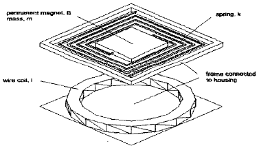
Figure 3. Diagram of the mass-spring vibration-based power generator [6]

where w = angular input vibration frequency, w0 = resonant frequency of mass-spring resonator, Y0 = amplitude at resonance, ee = the electrical damping factor, e is the total damping factor of the system.
At the resonant frequency of the mass-spring, the power is maximized and is equal to

A major component in the performance of the micro power generator is the design of the spring. Some design considerations are the amplitude of resonance, the fatigue life and the micromachining compatibility. These characteristics can be designed for by exploring the spring geometry and the spring material. One significant discovery was made on the movement of the spring suspended magnet: the generator produced significant voltage output at higher frequencies with low vertical vibrational magnitude due to second and third harmonic resonance from cyclic rotation of the mass. Horizontal vibrational movement contributed to changing the magnetic flux allowing greater current induction.
By rectifying the ac output of this power generator, a DC output voltage of 2.3V at 40uA for 100uW power was realized. This device was successful in generating enough power to operate a small infrared transmitter circuit. Some of the advantages of this design are the precise control of the mechanical resonance which is necessary to produce an efficient generator and the batch fabrication which will allow low-cost mass production of commercially viable generators [6].
However, despite the claim of this being a MEMS device, it is not a device fabricated on silicon substrate. It is a laser-micromachined device which is created off-chip to power a packaged circuit. As a result high parasitics associated with driving large package loads will affect the performance of the device. The fabrication constraints of the copper material and the required vertical displacement of 200 to 300um may prevent integration with the circuits it powers onto a single IC, which is one of the goals of MEMS power generation.
Thermal energy as an external energy source for MEMS power generation
Research has also focused on realizing power generators that use heat as its energy source. The advantage of thermal energy is that large quantities can be found in the environment and can be artificially produced by chemical reactions. The conversion of heat energy to electrical energy can be performed with the use of a thermopile, a series of thermocouples that, when heated, generate an electric current between its two terminals. This type of current generation is known as the Seebeck effect. Thermocouples are wires with two parts, each made from a metal from the thermoelectric series of elements. The wire is bent at the metal junction and produces current when there is a temperature difference between the thermocouple ends and the junction. The advantage of using thermopile is that it is simple and has no moving parts. Two devices using thermoelectric conversion of power are described: the first uses radiant heat as its energy source and the second uses the internal combustion of air and fuel.
Thermoelectric Micro Power Generator Utilizing Self-Standing Polysilicon-Metal Thermopile
The first thermoelectric power generator under discussion taken from [2] converts ambient heat energy into electrical power by the use of a thermopile. The conceptual drawing and a profile view of the thermopile power generator are shown in Figure 4. The generator is composed of a heat absorber and a thermopile composed of an array of thermocouples fabricated atop a silicon substrate. An oxide separates the cold contacts of the thermocouples from the silicon substrate. During operation, an external heat source radiates energy onto a heat absorber, which evenly distributes it over the contact layer. This heat is shared by the hot contacts of the thermocouples in the thermopile. The temperature difference between the hot contact at the heat absorber layer and the cold contact at the silicon substrate surface and the properties of the thermopile will determine the amount of power produced.
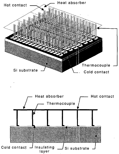
Figure 4. Diagram of self-standing thermopile fabricated on a silicon substrate (Above) and a profile cutaway of the thermopile (below)
A diagram of the thermocouple is shown in Figure 5. The thermocouple used here is composed of a n-type polysilicon layer and a gold/chromium (Au/Cr) composite layer. The tip of the wire at the bend is the hot contact and the two ends of the wire are cold contacts. The hot and colt contacts of the thermocouple are approximately 1mm distance from each other. The voltage output of the thermopile is determined by the Seebeck coefficients, the temperature difference of the two materials and the number of thermocouples:

where N is the number of thermocouples, alpha1 and alpha2 are the Seebeck coefficients of the thermocouple sections and T1 and T2 are temperatures of the hot and cold contacts, respectively.

Figure 5. Thermocouple dimensions and materials
The thermopile design in this generator uses vertical thermocouples without a membrane to realize greater thermal isolation between its hot and cold contacts [2]. The only connection between the hot and cold contacts is the thermocouple wire itself. The realization of the vertical structure is made possible by the fabrication of a MEMS hinge. Results from testing shown that the thermocouple under a 307K black body source generates around 110uV at a 2mm distance and around 50uV at a 7mm distance from its source [2].
A Combustion-based MEMS Thermoelectric Power Generator
Chemical generation of power is becoming a highly feasible as MEMS devices capable of fluid manipulation are being explored. In [1], a combustion-based power generator that converts heat energy from combustion into electrical energy is proposed. The advantage of chemical based fuels is that when they react with air, they can release 10-1000 times more energy power per unit mass than batteries [1].
A photograph of the generator is shown in Figure 6a and a conceptual drawing is shown in Figure 6b. The combustion-based power generator is composed of a silicon substrate with an etched channel capped by a thin membrane, a thermopile with cold contacts that mount to the silicon substrate edge and hot contacts that sit on top of the membrane and a catalyst that sits within the chamber, aligned with the hot contacts.
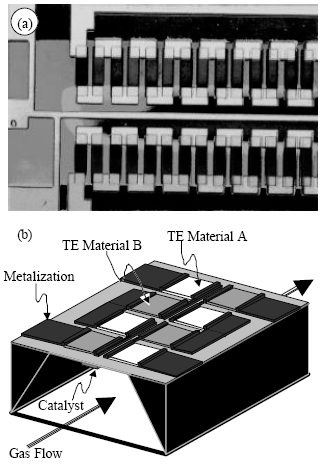
Figure 6. (a) Top view photograph of the combustion-based power generator (b) Diagram of the combustion-based power generator
During operation an air-fuel mixture is passed into the chamber as shown in Figure 6b. The air-mixture diffuses onto the membrane where they react with the catalyst, generating heat. The heat is channeled to the thermopile hot contacts on the topside of the membrane and is subsequently converted into electrical power. The heat on the thermopile generates electricity much like the thermopile discussed previously in [2]. The reaction produces water and carbon dioxide, which is passed through the opposite end of the chamber.
The combustion of air and fuel, despite its low efficient, still produces a much higher power density than batteries. Such a generator would use fuel cells and is thus more suitable for portable applications where fuel replacement opportunities are available than for distributed networks in large areas where the generator is inaccessible. Also, thermoelectric catalytic combustion is more advantageous than other heat engines because of simplicity, lack of moving parts, and is ideal for miniaturization [1]. However, the main problem with combustion-based generators is that despite higher power densities, the fuel supply still needs to be replenished. Where shelf life or replacement accessibility is limited, chemical power supplies may not be optimal [6]. Another major disadvantage of combustion-based generators is that significant amounts of waste heat must be removed, limiting their application to systems where heat removal to the environment is possible [7]. Therefore this type of generator may not be suitable for personal electronic devices like PDAs and cell phones, but rather more industrial and military types of applications.
Hybrid Combustion and Radiant-based Thermoelectric Power Generator
The hybrid power generator introduced here is an upgraded version of the combustion-based thermoelectric power generator from [1] that has the added capability of deriving power from an external radiant black body using techniques described by [2]. The goal of the hybrid is to combine two related methods of power generation into a single device in order to harness the capabilities of both in a portable system. The hybrid device is composed of a combustion channel created on a silicon substrate and a catalyst to facilitate the air-fuel combustion of the system. The thermocouples are situated on top of the chamber as shown in the conceptual drawing in Figure 7. However, the configuration of the thermocouples has been changed to allow for the utilization of an external heat source as well as heat from the combustion chamber. The thermocouples fabricated on top of the substrate have built in hinge mechanisms that allow them to orient toward either the combustion chamber or the heat absorber layer. This results in a dual sourcing of energy for thermoelectric power generation.

Figure 7. Diagram of dual-source thermoelectric hybrid power generator

Figure 8. Proposed fabrication processing steps for the dual-source hybrid power generator
The proposed fabrication of the dual-source, hybrid device is a combination of the steps found in the thermoelectric radiant power generator and the combustion-based generator. The proposed fabrication process is shown in Figure 8 and are described here:
- Coat silicon substrate with low-stress silicon nitride
- PSG (phosphosilicate glass [oxide]) deposition by APCVD (Atmospheric pressure chemical vapor deposition)
- Poly-Si deposition by LPCVD (Low pressure chemical vapor deposition)
- PSG deposition by APCVD and poly-Si impurity doping
- Poly-Si patterning by reactive ion etching (RIE)
- Au/Cr deposition, patterning and wet-etching
- Release is performed by HF wet-etching, NH4F rinsing, hydrophobic treatment, methanol rinsing and baking.
- Etch the channel into the wafer using KOH in a single-sided etch setup.
- Create the catalyst by e-beam depose using a specially microfabricated self-aligned shadowmask
- Configuration of the number of thermopiles used for the combustion generator and for the heat absorber. Thermocouples are bent downward against the chamber membrane to absorb combustion heat or vertically upward to absorb black body radiant heat.
- Placement of heat absorber above device in contact with vertical thermocouples
The hybrid design has numerous advantages in terms of configurability and application versatility. Setting the orientation of the thermocouples configures the number of thermocouples used to produce voltage from radiant energy and from combustion energy. Since the orientation of the thermocouples is determined after fabrication, the number of thermocouples used for radiant energy and combustion energy can be set based on application requirements. There are three main configuration options of the thermocouples:
- All thermocouples are configured for the combustion chamber. This maximizes the amount of power obtained from the combustion reaction. This configuration is similar to [1] except the thermocouples need to be formatted downward towards the combustion chamber and the heat absorber is not needed.
- All thermocouples are configured for the ambient heat absorber. This maximizes the amount of power obtained from a radiant source. This configuration is identical to [2] and the extra processing steps used to facilitate combustion are not used.
- Some thermocouples are used for combustion and some for radiant heat. Using a combination of external heat and internal heat thermocouples exploits the power of the hybrid design. Imagine a system whose primary power source comes from the air/fuel combustion and whose secondary power source comes from external heating. This method can vastly increase the lifetime of the power supply and reduce the requirements for the combustion design.
In considering the hybrid configuration of the generator, the thermocouples need not be used for power generation at all. Instead, the voltage generated from some or all of the radiant thermocouples can be used in temperature sensing. As a result, the hybrid generator can be used as a self-powered generator and integrated temperature sensor. The wiring of the thermocouples to the external circuitry will ultimately determine the role of the thermocouples within the system. If the wiring is performed on the IC during the layout process, the target application of the device needs to be determined before fabrication. However, if the control circuitry is off-chip and routing is done by bond wires, the configuration of the device can be done after fabrication.
Convertible power generator device
Another possibility is to make the system convertible during operation. This is accomplished by electrodes that pivot the orientation of the thermocouples. The advantage of this is the full operation in one state or another, thereby maximizing the amount of power that can be harnessed from either the internal or external heat energy. However, some disadvantages include more complicated and power consuming circuitry, which may outweigh the benefits of the convertible design and less efficient isolation of the hot and cold junctions due to the limited actuation angle of the thermocouples. The other disadvantage is the power required to drive the electrodes to move the thermocouples into the desired location. Another problem that would need to be worked out is possible stiction of the thermocouples. As the thermocouples pivot between the combustion chamber’s membrane surface and the heat absorber, their tips may wear or get stuck in one state or another.
Nevertheless, a proposed fabrication process is illustrated in Figure 9. The proposed fabrication steps of the convertible dual-source, hybrid device is similar to that of the non-convertible device. However, the main difference is the implantation of electrodes use to perform the actuation, the thickness of the column and the placement of the heat absorber relative to the thermocouples. The steps shown in Figure 9 are:
- Coat silicon substrate with low-stress silicon nitride
- Metal electrode deposition
- PSG deposition by APCVD (Ambient pressure chemical vapor deposition)
- Poly-Si deposition by LPCVD (Low pressure chemical vapor deposition)
- Metal electrode deposition
- PSG deposition by APCVD and poly-Si impurity doping (phosphosilicate glass [oxide]) (Atmospheric pressure chemical vapor deposition)
- Poly-Si patterning by reactive ion etching (RIE)
- Au/Cr deposition, patterning and wet-etching
- Release is performed by HF wet-etching, NH4F rinsing, hydrophobic treatment, methanol rinsing and baking.
- Etch the channel into the wafer using KOH in a single-sided etch setup.
- Create the catalyst by e-beam depose using a specially microfabricated self-aligned shadowmask
- Place heat absorber above thermocouples
- Convertible dual-source power generator in the radiant thermoelectric mode
- Convertible dual-source power generator in the combustion-based thermoelectric mode
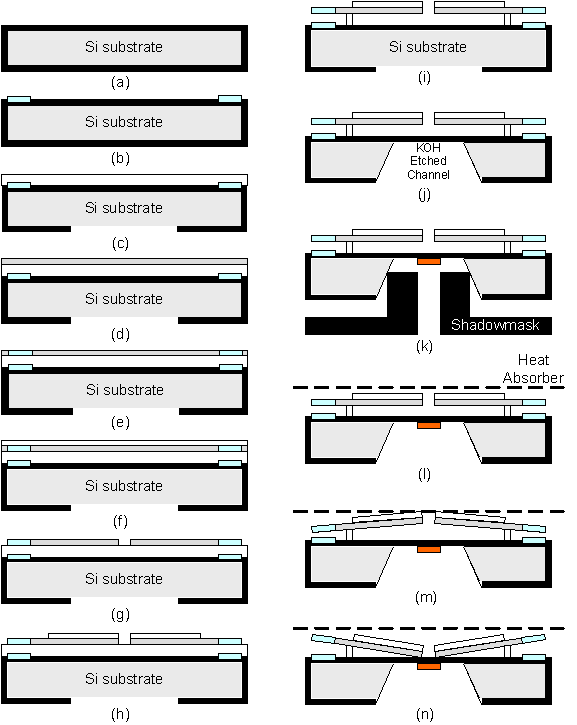
Figure 9. Proposed fabrication processing steps for the convertible dual-source hybrid power generator
In the convertible hybrid’s structure, the thermocouples are actuated by electrostatic forces generated by electrode plates fabricated on the ends of the thermocouple and on the substrate. The location of the electrodes on the thermocouple, ensures that they do not interact with the operation of the thermocouple. The mechanism that allows for pivoting need not be complicated and is composed of a thin, flexible post attached to the base of the thermocouple as shown in the figure.
Estimation of power generated from the hybrid and an application
A model of the thermocouple is shown in Figure 10 from which the voltage output of the thermocouple is calculated.

Figure 10. Equivalent circuit of the thermocouple [2]

where alpha is the Seebeck coefficient and T is the temperature. The voltage contribution of the Cr material is cancelled out since there is no temperature drop across the two ends of the Cr section. Using thermocouples is versatile in that different parallel and series combinations of the thermocouples can be used to configure the generator based on application needs. Configuration is done simple by wiring the thermocouples in series for more voltage output or in parallel for more current capability or both to meet needed voltage and current specifications. The Seebeck coefficients for this metal types used in this thermocouple are taken from [8] and shown in Table 1.

Table 1. Seebeck coefficients for the thermocouple materials in uV/K [8]
Radiant heat
In [2] the voltage capability of a single thermocouple is measured in the presence of a black body 307K radiating energy at a variable distance away. The temperature of 307K is chosen to simulate heat from a human body. Experimentally, a single thermocouple is capable of producing 110uV from a 307K radiant blackbody 2mm away and 50uV from 7mm away [2]. Additional experimental results from [9] show that a set of 10 thermocouples is capable of producing as much as 8.2mV at about 1mm away and at least 6mV at even a distance of 10mm away. This output voltage is significant in that a 10-by-10 array of 100 thermocouples can produce 0.06V. The current output of the thermocouple is equal to the ratio of the voltage output and the resistance of the thermocouple [10]. However, one major limitation in terms of estimating the current output of the device is that the resistance of materials varies with respect to temperature. This makes it difficult to estimate a general current output of the thermocouple unless a specific temperature is given.
Combustion heat
While the thermocouples used in [1] are different from those in [2], the basic operation of the combustion-based generator is unchanged. We therefore assume that the power generated from the thermocouples in [1] is also achievable in our hybrid design. If the thermocouple from [2] proves to be a limitation in the amount of power extracted from the combustion, the [1] thermocouple can always be fabricated instead if needed.
In order for the catalytic combustion to occur in the chamber, a start-up heater is used to ignite the reaction. During start-up, the heater power is slowly increased until reaching the ignition power (around 90mW from [1]). Once this is achieved, the combustion is ignited and the start-up heater is turned off. Power in the heater decreases until it reaches 0mW. At that time, autothermal catalytic combustion of the fuel will take place.
The start-up of the combustion is performed only once to initiate the autothermal catalytic reaction. As this may seem cumbersome, imagine that start-up heater is a separate unit that a user can operate onto the generator before being put into service. Although no actual data is presented, [1] claims a possible 7V output from the combustion based design. However, we will assume that during autothermal operation, a steady voltage of 1.25V is be realized [1].
IR transmission of data
An infrared transmission system is used for the application example of the hybrid generator similar to [6]. The chosen transmitter IC is capable of 3-bit transmission. However, due to the power constraints, the IR transmitter will be used simply to send a single data pulse. Since the output current of the power generator is too small to directly power the IC, it will charge an appropriately sized capacitor to provide enough power for the IR transmitter to produce a bit pulse for 10ms. The periodic signal resulting from charging and discharging of the power supply capacitor can be used as a type of activity beacon, notifying the receiver, either another unit or a base station, that the system is still active. This type of application can be used as part of a sensor network with limited power or on some wearable device from which radiant heat energy can be obtained from a user.
A low-power 8-pin, 3-bit infrared encoder is used as a digital transmitter. The IC used is called the Tiny-IR from Reynolds Electronics [11]. The Tiny-IR can be configured for either long-range, up to 100’ operation or short-range 15-20’ operation. The wiring diagram for the Tiny-IR in short range configuration is shown in Figure 11. The transmitter is composed of the Tiny-IR chip, a 4MHz ceramic resonator, a resistor and an infrared LED. In the short-range configuration, the infrared LED can be driven by the chip. The transmitter has three connections, Button #1, Button #2, Button #3 corresponding to the three data bits. When a Button input is grounded, a corresponding data signal is sent. In our application, however, only one data bit controlled by Button #1 is used. Button #2 and Button #3 are left open. Normally a physical button would ground the Button #1 pin when depressed. However, in our application, control of the pulse transmission is shifted from Button #1 to the power supply since the supply will periodically turn on and off as the supply capacitor is charged and discharged.

Figure 11. Tiny-IR transmitter in 15-20ft range configuration

Table 2. Specifications for the Tiny-IR encoder transmitter
As stated before, the power generator will charge a capacitor that will supply enough power for the IR transmitter to send its signal. In order to calculate the capacitance needed to power the encoder, the specifications in Table 2 and the generator output capabilities need to be estimated.
According to the specifications, the Tiny-IR encoder requires a voltage supply of at least 3.0V and a current capability of 2.83mA. However, this current requirement is for the IC alone. The IR LED’s current requirement for maximum range operation of 20ft is of 24mA as shown in Figure 11. Therefore, during transmission, the system needs about 26.83mA of current at a 3V supply voltage for an arbitrarily chosen duration of 10ms. The 3V supply requirement is actually somewhat high and the chip can possibly operate at a lower supply, but because an actual IC is unavailable for testing, the minimum operating supply of 3.0V is assumed. We choose a target voltage supply of 3.1V to allow the circuit to operate for the required duration before turning off.
Also, because the actual generator device is unavailable for experimentation, the estimate is based on data from [1,9]. To realize the 3.1V voltage supply, two combustion chambers, each producing 1.25V during autothermal operation, can be put in series to obtain 2.5V. The remaining 0.6V can be extracted from the radiant energy thermocouples. The performance data for the thermocouples is [2] and [9] seem to be contradictory, and so [9] will be used in this estimate since it shows better performance. According to [9], ten thermocouples can produce a maximum of 8.2mV from a 307K black body source 1mm away. As a result, 730 thermocouples are needed to realize 0.5986V. Therefore, utilizing two combustion chambers in series with 730 radiant thermocouples can produce the required 3.0986V.
In order to supply enough current to the transmitter, the current output of the combustion chamber thermocouples and the radiant black body thermocouples must be estimated. According to [1] a power output around 10uW is produced for a reaction temperature of around 350 degrees. If at this temperature, the combustion chamber is producing the 1.25V, current output is about 8uA. Also, sets of the 730 radiant energy thermocouples need to be put into parallel in order to produce 8uA. To solve for the number of sets needed, the thermocouple current output needs to be computed from the thermocouple output voltage and thermocouple resistance [10].

Figure 12. Thermocouple structure [2]

From [9], ten thermocouples in series produce a maximum of 8.2mV, so a single thermocouple is capable of producing 0.82mV. Then the current output of a single thermocouple is then

This means in order to match the 8uA from the combustion chamber thermocouples, there needs to be 8uA/2.05uA = 3.9 parallel sets of 730 series thermocouples. If 4 sets are used, this results in 2920 thermocouples dedicated to harvesting radiant energy. This alone can be realized by a 55 x 54 (= 2970) thermocouple array. This may seems like an extremely large number of thermocouples to produce little power, but from Figure 5, each thermocouple occupies a surface area of about 1700um by 500um and so a total area of about 2.5245mm2 is required to realize the radiant heat thermocouples. This is still a reasonably small size for a portable device. Note that although the number of thermocouples used for the combustion is not stated in [1], it is most likely much smaller than for the radiant energy harvesting. The thermocouples for the combustion reaction can then be integrated with the radiant energy thermocouples as proposed.
Now that we have all the required parameters, the capacitor size and charge time can be determined. The size of the capacitor needed for the power supply is computed the same way as in [6]. The supply capacitance needed based on the specifications of the system and the voltage capability of the generator for a 10ms pulse is

From the capacitance calculation and the output capabilities of the generator, the initial charge time with T=350K, P=10uW, and Igen=8uA is

After the initial charge, the IR transmitter will send a signal for 10ms. After that time, the voltage across the capacitor will not be enough to power the system and will drop only slightly below the 3.0V supply requirement. Therefore, it will not need to charge from 0V again and will take much less time to charge the capacitor to power the circuit. As a result, we charge the capacitor for only 0.1V. A generic illustration of the charging and discharging behavior of the capacitor is shown in Figure 13.
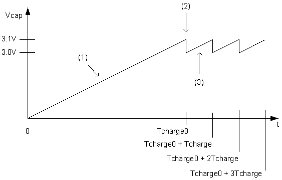
Figure 13. Illustration of charging and discharging behavior of the capacitor. (1) The capacitor initially charges from 0V to 3.1V for a time Tcharge0. (2) The IC is turned on, emits the signal and the voltage drops below the required operation voltage. (3) The capacitor recharges again at the same rate, but for a much shorter time. Steps (2) and (3) are repeated.
Subsequent charges will take

which is a reasonable time. Here, we use a generator that requires a very long initial charge, but fairly short subsequent recharges. Specifications on the power generator can be modified to change these times depending on application requirements.
Conclusion
Power generation techniques using MEMS fabrication or microfabrication were investigated. Four different micro power generators were studied and discussed. The micro power generation schemes are a vibration-induced capacitive generator, a vibration-induced inductive generator, a thermoelectric radiant heat-based generator and a thermoelectric combustion-based generator. The advantages and disadvantages of the power generators were discussed. Power generation from kinetic energy seems promising in that the resource from the environment can be unlimited. However, it is still in its development stages and not enough useable power can be generated from these devices. The exception is for [6], but the components here are not produced in a MEMS technology and most likely do not allow for mass-production. Also, fabrication of the device apart from the circuitry is unattractive due to increased capacitances. Thermoelectric power is very promising because of its simplicity, but combustion-based thermoelectric generation still requires a refueling of resources.
From studying the thermoelectric power generators, a hybrid generator utilizing design concepts from [1] and [2] is introduced. The hybrid generator has a thermopile that can be configured to extract power from both ambient radiant energy as well as from a microfabricated combustion chamber. The advantage of such a device is longer power source lifetime. An infrared transmitter application based on a low power encoder IC is discussed and its power requirements are estimated. From a voltage requirement of 3V and a current requirement of 26.83mA, a hybrid generator configuration using two combustion chambers generators and an array of 2970 radiant thermocouples is proposed to power the chip. Such a generator will be able to periodically power the transmitter for 10ms using a 2.683mF supply capacitor. The initial charge time for the capacitor is a very long 1039.6625 seconds, but subsequent charges require only 33.5375 seconds. This makes the power generator practical enough to use in this transmitter application.
Acknowledgment
Special thanks to Raj Amirtharajah for his help
References
[1] S. Schaevitz, A. J. Franz, K. F. Jensen et al., “A Combustion-based MEMS Thermoelectric Power Generator,” The 11th International Conference on Solid-State Sensors and Actuators, Munich, Germany, June 10-14, 2001, Available at: http://jensengroup.mit.edu/publications/SamTE.pdf [2] T. Toriyama, M. Yajima and S. Sugiyama, “Thermoelectric Micro Power Generator Utilizing Self-Standing Polysilicon-Metal Thermopile,” Micro Electro Mechanical Systems, 2001. MEMS 2001. The 14th IEEE International Conference on , 21-25 Jan 2001, Page(s): 562 -565, Available at: http://ieeexplore.ieee.org/iel5/7264/19601/00906603.pdf?isNumber=19601&prod=IEEE+CNF&arnumber=906603&arSt=562&ared=565&arAuthor=Toriyama%2C+T.%3B+Yajima%2C+M.%3B+Sugiyama%2C+S.%3B [3] J. Boland, Y.H. Chao, Y. Suzuki and Y.C. Tai, “Micro Electret Power Generator,” Micro Electro Mechanical Systems, 2003. MEMS-03 Kyoto. IEEE The Sixteenth Annual International Conference on , 19-23 Jan. 2003, Page(s): 538 –541, Available at: http://ieeexplore.ieee.org/iel5/8460/26644/01189805.pdf?isNumber=26644&prod=IEEE+CNF&arnumber=1189805&arSt=538&ared=541&arAuthor=Boland%2C+J.%3B+Yuan-Heng+Chao%3B+Suzuki%2C+Y.%3B+Tai%2C+Y.C.%3B[4] T. Genda, S. Tanaka and M. Esashi, “Design of High Power Electrostatic Motor and Generator Using Electrets,” IEEJ Transactions on Sensors and Micromachines Extended Summary, Sep 2003, Volume 123-E Number 9, pg. 331, Available at: http://www.iee.or.jp/honbu/back_number/journal/index_back_number/2003/2003_09e_01.pdf
[5] T. Sterken, K. Baert, R. Puers and S. Borghs, “Power Extraction from Ambient Vibration,” Proceedings of SeSens 2002, November 29, 2002, Veldhoven, the Netherlands, Available at: http://www.stw.nl/programmas/sesens/proc2000/sterken.pdf [6] W. J. Li, T. C. H. Ho, G. M. H. Chan et al, “Infrared Signal Transmission by a Laser-Micromachined Vibration-Induced Power Generator,” Proc. 43rd IEEE Midwest Symp. On Circuits and Systems, Lansing, MI, Aug 8-11, 2000, Pages(s): 236-239, Available at: http://www.cse.cuhk.edu.hk/~phwl/papers/gen_mwcs00.pdf [7] O.M. Nielsen, L.R. Arana, C.D. Baertsch et al., “A Thermophotovoltaic Micro-Generator for Portable Power Applications,” The 12th International Conference on Solid State Sensors, Actuators and Microsystems, Boston, June 8-12, 2003, Available at: http://jensengroup.mit.edu/new_students/OleNielsenTransducers03.pdf [8] Y.C. Tai, “Thermal Sensors,” [Online Document] EE 40 – Introduction to Sensors and Actuators, Lecture Notes from May 7: Thermal and Infrared Sensors, pg. 13, Available at: http://touch.caltech.edu/courses/EE40%20Web%20Files/Thermal%20and%20Infrared%20Notes.pdf [9] Masakazu Yajima, Toshiyuki Toriyama and Susumu Sugiyama, “Self-standing Polysilicon-metal Thermopile for Accesory Micro Power Generator,” [Online document] Accessed [2003 December 3], Available at: http://www.ritsumei.ac.jp/se/~sugiyama/research/re_3.2e’.html [10] J. Jackle, “The origin of the thermoelectric potential,” [Online document] November 2000, Accessed [2003 November 26], Available at: http://www.uni-konstanz.de/physik/Jaeckle/papers/thermopower/thermopower.html [11] Reynolds Electronics, “Tiny-IR,” [Online document] Accessed [2003 November 25], Available at: http://www.rentron.com/3-bit-infrared.htm, http://www.rentron.com/remote_control/tinyir.pdf, http://www.rentron.com/Files/TINY-IR2.pdf [12] A.G. Andreou, “Sheet Resistance,” [Online document], Accessed [2003 December 2], Available at: http://www2.ece.jhu.edu/faculty/andreou/487/2003/LectureNotes/SheetResistance8e.pdf